ESP32 driving swimming pool roller shutter
It is know that tech people are working hard during day and night. And what a frustration to see that time has come and you must stay 1’30 in front of the window, thumb on the button, to close the roller shutter due to french legal decision.
As every tech person knows, on each problem there is a solution ! (One day I will detail my irrigation system 😜) I was looking for an easy and straight forward solution. I came accross a Youtube channel @Abrège discussing the ESP32 system linked to Home Assistant. Let’s detail everything…
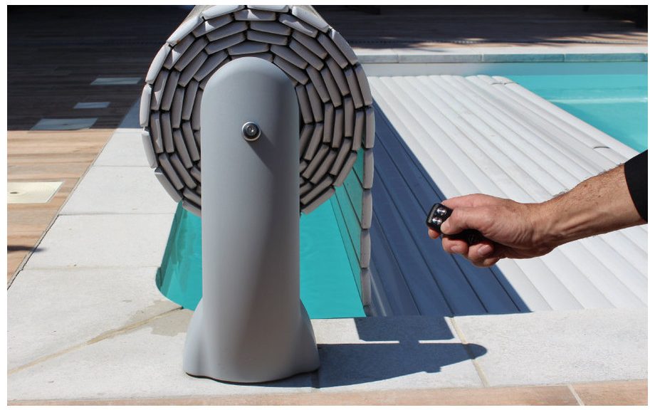
What I have in mind…
I already have a system that allows me to close this roller shutter but the security and poor connection system force me to change. There is a key system to manually open or close it.
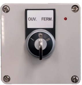
Quick idea was to bypass key system directly. We can do it with a relay module. As we can see, there is 3 states. I can easily imagine that nothing happen on the 0 and contact is done on Open or Close. Now we need some intelligence to handle this relay. @Abrège was speaking on easy part to integrate ESP32 to HomeAssistant. As I am running a home server (RunTipi) based on Kubernetes, easy and plug and play, with a HomeAssistant container, it was a perfect solution. Another tips was to select voltage value aligned with relay and ESP32 : 5V.
Here is the small design :
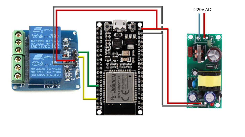
As I am not an electronics engineer, I did not know how to protect this setup (by adding resistance or thing like that). Erratum, only 24VDC was coming from the pool house 😅. Hopefully for the security !
Furniture
Amazon was my best friend 😁. Here is the details :
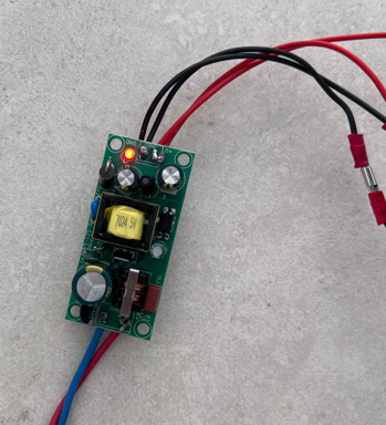
- AC to DC converter board : 8€ (Erratum, hopefully there is no 220VAC comming near the pool. I redirected to a 24VDC to 5VDC converter)
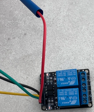
- 5V relay 2 chanels : 7€
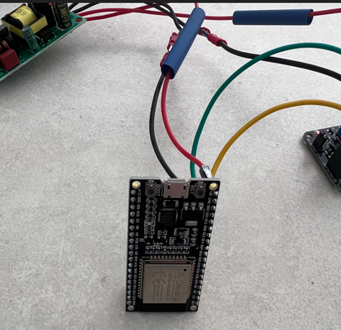
- ESP32 : 10€
- JST SM connectors box : 10€ (only need few, approx 20cts)
- Electrical wires : 20€ (really using 40cms, so 50cts)
- Soldering Iron (for the 220 AC side) and few Wago
I also added some « easy-to-plug » connectors on my version but they was only for testing purpose.
Here is some pics of the setup :
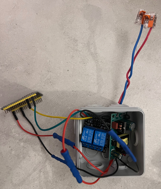
Easy setup
When setup was done, time is to unplug ESP32 to « configure » software. First small joke, as I am not on HAOS directly but through RunTipi which is container installation. I added in my docker-compose an extra configuration for ESPHome :
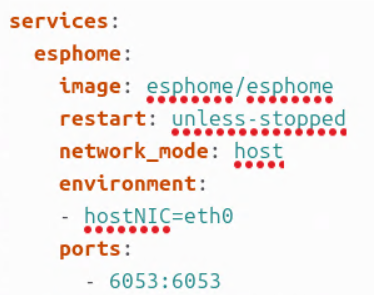
Time not to setup our ESP32 firmware by navigating on ESPHome container <yourAddress:6052>:
- Connect your ESP32 to your computer. I had to install drivers on windows11 and don’t forget to use data USB Cable !
- Add a new device on ESPHome
- Name it
- Select hardware through list (i have selected ESP8266 for reference given previously)
- Then do not install now. Edit file and configure your wifi that boar will connect on.
- Save the new configuration
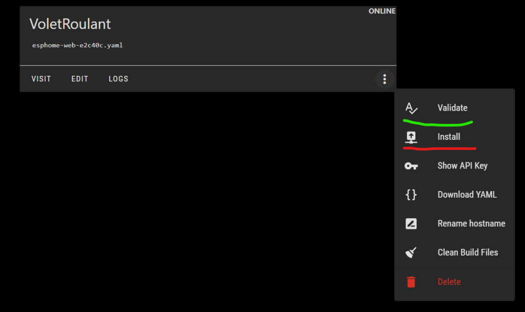
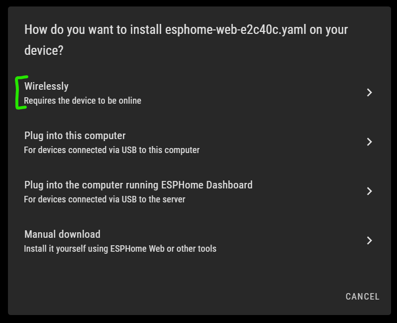
- Now click on install and don’t forget to click on Boot buton directly on the board
If install is successfull, then you will see your board as active and your ESP32 visible in your network list.
Software part
Once installed on your network, you have access to your ESP Home instance that list all you ESP.

When editing the code, as a long time software developper, it was the easiest part 😁
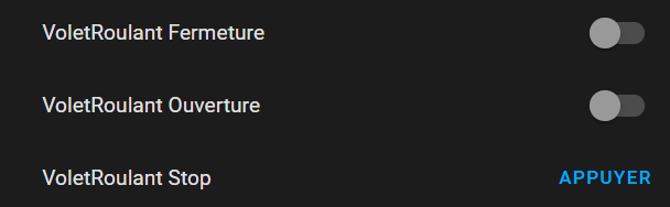
Here is my small Yaml Code (It is the final version):
substitutions:
  name: esphome-web-e2c40c
  friendly_name: VoletRoulant
  relay_restore_mode: ALWAYS_OFF

esphome:
  name: ${name}
  friendly_name: ${friendly_name}
  min_version: 2024.6.0
  name_add_mac_suffix: false
  project:
    name: esphome.web
    version: '1.0'

esp32:
  board: esp32dev
  framework:
    type: arduino

# Enable logging
logger:

# Enable Home Assistant API
api:

# Allow Over-The-Air updates
ota:
- platform: esphome

# Allow provisioning Wi-Fi via serial
improv_serial:

wifi:
  ssid: "MYRZO"
  password: "YOURPASSWORD"

  ap:
    ssid: "Esp32FallbackRZO"
    password: "ANOTHERPASSWORD"

# In combination with the `ap` this allows the user
# to provision wifi credentials to the device via WiFi AP.
captive_portal:

dashboard_import:
  package_import_url: github://esphome/example-configs/esphome-web/esp32.yaml@main
  import_full_config: true

# Sets up Bluetooth LE (Only on ESP32) to allow the user
# to provision wifi credentials to the device.
esp32_improv:
  authorizer: none

# To have a "next url" for improv serial
web_server:

switch:
  - platform: gpio
    pin: GPIO21
    name: "Ouverture"
    icon: "mdi:icon7-unlock"
    id: relay1
    interlock: [relay2]
    restore_mode: ${relay_restore_mode}
    on_turn_on:
    - delay: 130s
    - switch.turn_off: relay1

  - platform: gpio
    pin: GPIO22
    name: "Fermeture"
    icon: "mdi:icon7-lock"
    id: relay2
    interlock: [relay1]
    restore_mode: ${relay_restore_mode}
    on_turn_on:
    - delay: 130s
    - switch.turn_off: relay2

button:
  - platform: template
    name: "Stop"
    id: Stop
    icon: "mdi:icon-warning-sign"
    on_press:
      - switch.turn_off: relay1
- switch.turn_off: relay2- I was not able to use secret… That is why you may see the password here.
- I had a problem about initial state during my tests that is why I use restore mode to ALWAYS_OFF (may be linked to dependency between switches).
To produce this code, I went to https://esphome.io/ That list all types of components that can be added in YAML. I also found small trigger between switches (disable the other when pressed) that can be usefull for my pool roller shutter as we can’t open and close it as the same time 😵.
First Test
As you seen previously there was some glitches on the switch state when starting/booting the ESP32. Shutter was closing or openning without any commands. I am not an electronic expert but my old embeded lessons spoke about initial state. So I quickly enabled the restore mode for the GPIO values. I also added Icons and Labels to be reflected inside Home Assistant. I also had to adjust delays for openning and closing.
Edit and deploy is quite easy (don’t forget to validate before).
Adjustments that can be « air deployed » ☁️ :
Installation
First installation was close to that :
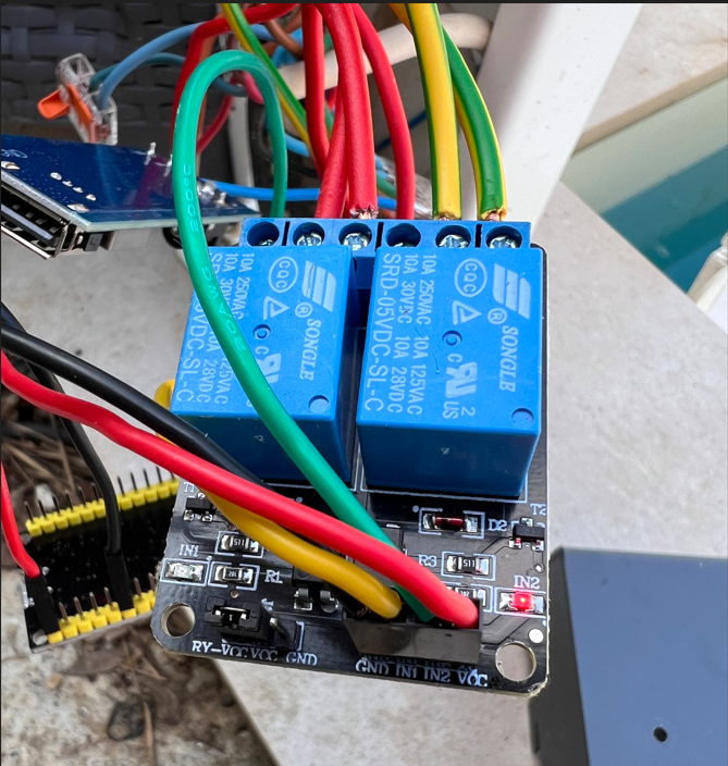
As you can see, IN2 LED is on and not the IN1. This mean it still was initial state issues.
I also was not satisfied because boards was navigating inside the compartment. So I created a small organisation board in 3D to put all the 3 cards :
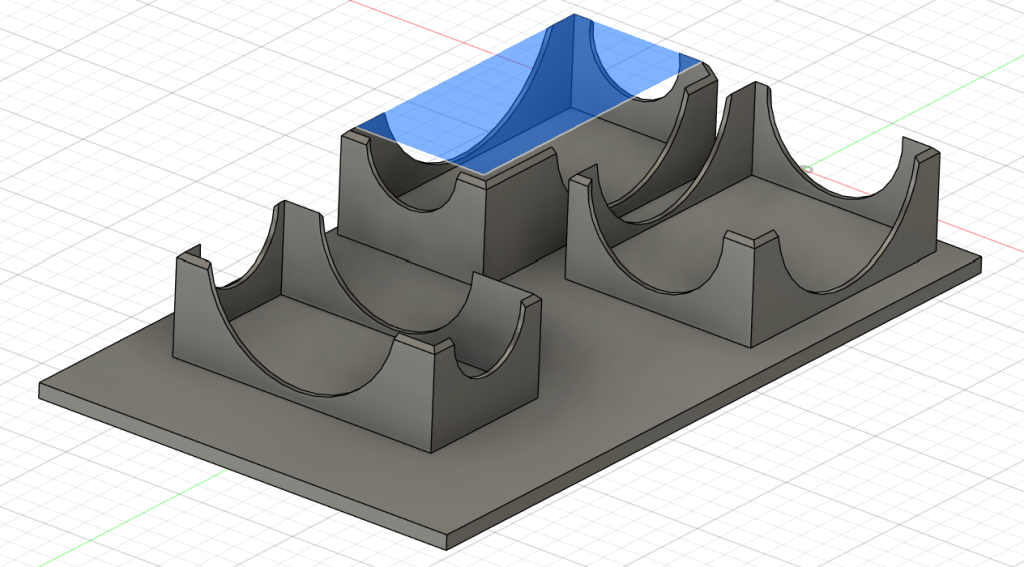
Thanks to Fusion360 and it’s « mm » measure precision, I only print two versions for fitting board correctly.
The final result is here :
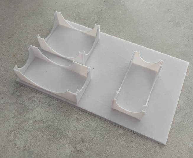
My AnyCubic Vyper is still working well !
Final Test
As a final test, I reboot multiple times with all GPIO combination state to be 100% sure. I also tested with board controls. Everything seems fine !